Dr. Thapar's patient from 1991:
Persistent fifth arch with Coarctation and TOF.
Some images worth learning from are posted here (Note: Most of them are plagiarised. But, sources are referenced)
7/28/2010
7/25/2010
Surgery: Pulmonary atresia - VSD, MAPCAs, Unifocalization
Staged repair of tetralogy of Fallot with pulmonary atresia and major aortopulmonary collateral arteries. Duncan, BW., Mee, RBB, et al. JTCVS 2003;126:694-702.
Treatment algorithm:
Freedom from reintervention (surgery or cath) after complete repair:
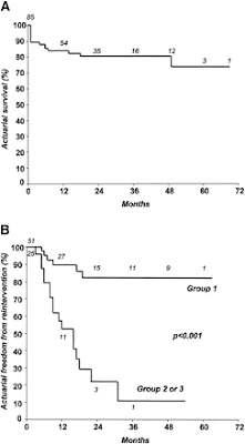
Frank Hanley group: (Circulation 2000)
V. Mohan Reddy et al. Circulation 2000;101:1826-32
Early and Intermediate outcomes after repair of pulmonary atresia with ventricular septal defect and major aortopulmonary collateral arteries.
Treatment algorithm
Treatment algorithm:
Survival after first surgery:
Freedom from reintervention (surgery or cath) after complete repair:
Frank Hanley group re: Surgical creation of "A-P window"
Rodefeld, MD. et al. JTCVS 2002;123:1147-54.
Selection criteria for surgical creation of A-P window:
1) Presence of centrally confluent pulmonary arteries (1 - 2.5 mm in diameter with well-developed peripheral arborization)
2) Multiple, hypoplastic AP collaterals that communicated with true pulmonary artery system
3) Presence of marked cyanosis
Avoid this procedure in the following situations:
1) High flow from MAPCAs
2) Isolated supply from MAPCAs (indicates native PAs do not have good peripheral arborization...to stand the high flow-high pressure from aorta)
3) Native PAs > 2.5 mm and
4) non-confluent native PAs.
Frank Hanley group: (Circulation 2000)
V. Mohan Reddy et al. Circulation 2000;101:1826-32
Early and Intermediate outcomes after repair of pulmonary atresia with ventricular septal defect and major aortopulmonary collateral arteries.
Treatment algorithm
Also see:
7/23/2010
Anatomy: Preop. evaluation of pulmonary arteries/MAPCAs in Pulmonary Atresia - VSD
Review article
1) McGoon ratio:
(Diameter of RPA/DAo + Diameter of LPA/DAo)
Normal 2.1
Adequate for VSD closure 1.2
Inadequate <0.8 for VSD closure
2) Nakata Index:
(CSA of RPA + CSA of LPA)/BSA
Normal value > 200 mm2/m2
> 150 mm2/m2 is adequate.
(Not usable preoperatively when MAPCAs are the major source of PBF & one-stage unifocalization + full repair is planned).
(> 200 for single ventricle repair, > 100 for 2-ventricle repair...check correctness of this statement first)
3) Total Neo-Pulmonary Artery Index (TNPAI) = APC index + Nakata Index
APC index is the sum of CSA of all usable APCs/BSA
>250 - suitable for one-stage repair including VSD closure (These pts. have low RV/LV pressure ratio postoperatively).
Critique of all these indices: These indices consider only the size of proximal vessel and not consider the condition of distal parts of the vessels (which may be stenosed, etc).
Also see:
MAPCAs in PA-VSD
Surgical Outcome (Journal Club blog)
Surgical Treatment algorithm
7/22/2010
MAPCAs - Pulmonary Atresia with VSD
Theories on the nature/origin of MAPCAs in Pulmonary Atresia with VSD.
It is speculated that MAPCAs are enlarged bronchila arteries in whom the broncho-pulmonary anastamosis has enlarged.
(First 2 images are from MA Norgaard et al. Eur J Cardio-thorac Surg 2006;29:653-8)
It is speculated that MAPCAs are enlarged bronchila arteries in whom the broncho-pulmonary anastamosis has enlarged.
(First 2 images are from MA Norgaard et al. Eur J Cardio-thorac Surg 2006;29:653-8)
The following 2 images are from Ingram Schulze-Nick et al. Circulation 2000;102 (Suppl III):III-142-III-147.
Also see, on this subject:
7/20/2010
Cath: Parallax Error and Foreshortening
Image from The Cardiac Catheterization Handbook. Morton Kern. 3rd edition (1999):
Cross reference: Imaging VSD
Cath: X-ray
(Extract from Morton Kern’s The Cardiac Catheterization Handbook. 3rd edition 1999)
X-ray tube: converts electrical energy into X-ray beam. Electron beams from a heated cathode are accelerated towards the rotating disc of anode. The electrons become X-rays upon contact with anode. But, only 0.2-0.6% of electrical energy provided is eventually converted into X-ray. This process generates extreme heat.
Three factors influence the X-ray image:
1) Electrical current (mA): Number of photons (electrical particles) generated per second. Increasing milliamperage increases quality of image. But, heat generated is the limiting factor. Of course, this increases radiation exposure to patient and increases scatter – leading to increase in exposure to lab personnel.
2) Kilovoltage level (kV): The wavelength of the X-ray beam. Higher the kV, shorter is the wavelength. Less tissue penetration. So, for obese patients, high kV is needed to get adequate penetration. But, high kV leads to poor resolution of the image. Higher kV also increases scatter and therefore, higher exposure to lab personnel.
High kV - short wavelength, uniform and better penetration. But, low contrast in image.
Low kV - provides better contrast in image.
High kV allows to keep mA low, but the trade-off is low-contrast in the image. A balance has to be struck. kV has more effect on image contrast than mA.
3) Exposure Time (s): Pulse width
ICU - Shape of arterial line trace
Two simultaneous arterial line traces are displayed below:
One from right radial A line and the other from right femoral A line.
Guess which trace is from which line from the shape of the trace.
One from right radial A line and the other from right femoral A line.
Guess which trace is from which line from the shape of the trace.
This is the uncropped image of the trace above, now has readings from these lines uncovered.
(Newborn, s/p coarctation repair and PA band)
7/14/2010
7/13/2010
Cath: Imaging VSD
Images from Kurt Amplatz's Radiology of Congenital Heart Disease (1992):
Cross reference: Parallax Error and Foreshortening
7/11/2010
ICU: Monitor - NIRS reading low
ICU: Monitor - s/p Norwood - Temporary pacemaker - Nitric Oxide
ICU: Monitor - Differential Cyanosis
Scenario 1:
6-hours old, term baby girl. 3.4 kg. Transferred from outside hospital for cyanosis noted at 2 hrs of age.
Oxygen saturation:
Preductal 100%
Postductal 81%
6-hours old, term baby girl. 3.4 kg. Transferred from outside hospital for cyanosis noted at 2 hrs of age.
Oxygen saturation:
Preductal 100%
Postductal 81%
Scenaio 2:
17 day old baby, born at home
Admitted via ER for cyanosis and respiratory distress.
Following is the monitor image:
"Reverse" Differential cyanosis is noted
Preductal saturation 87%
Postductal saturation 96%
What is the differential diagnosis?
ICU: Hypertension Management (Labetalol)
Beyond Nitroprusside and Esmolol infusions...Hydrallazine and Labetalol may be used as either bolus doses or infusions.
Article 2010 PCCM Publish ahead of print describes safety of Labetalol infusion in children
Lexi-Comp:
IV intermittent dose: 0.2 - 0.5 mg/kg/dose (Range 0.2 - 1 mg/kg/dose)
IV continuous infusion: 0.2 - 1.5 mg/kg/hr (Mean 0.8 mg/kg/hr; Max 3 mg/kg/hr)
Oral: 4 mg/kg/day in 2 divided doses (max. 20-40 mg/kg/day)
Duration of action: Oral - 8-24 hrs (dose dependent) IV - 2-4 hrs
Half-life: 5-8 hrs
ICU: Monitor - CVP trace analysis
4 mo. old, 1-hr postop. after repair of Tetralogy of Fallot.
HR was 171/min about 10 minutes ago. Suspicion of JET has risen.
Analyze CVP trace. Identify the waves.
Which is taller (a or v)?
What happened to c?
Where are X and Y decents?
There is doubt about sinus rhythm vs. JET. EKG is difficult to interpret. Can CVP trace help?
Labels:
EP,
Hemodynamics,
ICU,
Interpret this,
Monitor,
Pressure Trace,
Quiz
7/07/2010
ICU: Nitroprusside infusion and toxicity
Dose: Start @ 0.5 mcg/kg/min and titrate to effect.
Usual dose: 3 mcg/kg/min
Max. dose: 8-10 mcg/kg/min (Rarely, need >5 mcg/kg/min)
Half-life: 10 min
Metabolism:
Converted to cyanide in RBCs and tissue; Cyanide is converted in liver to thiocyanate. Thiocyanate is excreted in in urine.
Monitor for toxicity if:
1) > 4 mcg/kg/min for > 3 days
2) Liver dysfunction (Cyanide toxicity)
3) Renal dysfunction (Thiocyanate toxicity)
Monitoring parameters: HR, BP, pH (metabolic acidosis), Lactate level, Serum level of cyanide and thiocyanate
Cyanide toxicity:
Metabolic acidosis, Tachycardia, pink skin, decreased pulse, decreased reflexes, altered consciousness, coma, almond smell on breath, methemoglobinemia, dilated pupils
Normal: <> 2 mcg/ml
Potentially lethal: > 3 mcg/ml
CyanmetHb forms from the cyanide which is part of Nitroprusside molecular structure. This is more common in postop. cardiac patient because of availability of more Hb in plasma due to hemolysis during cardiopulmonary bypass. Antidote: Sodium thiosulphate or Sodium nitrite.
Thiocyanate toxicity:
Psychosis, blurred vision, confusion, weakness, tinnitus, seizures
Toxic: 35-100 mcg/ml
Fatal: > 200 mcg/ml
Source: Lexi-Comp's Pediatric Dosage Handbook 12th ed. (2005-6)
7/03/2010
Cath: Calibration for measurements during angiography
(Collected from postings on Pediheart several years ago)
Overall, use of catheters and external phantoms cause large errors due to (i) inaccurate measurement, (ii) foreshortening, (iii)distortion of reference object and (iv) displacement of object of interest from isocenter (as high as 28% error in measurement of PA size).
Marker pigtail with 1 cm markers
Marker wires (expensive)
Cut piece of the markers in the pigtail - attached to patients chest
(granted, there is a "small error" ~5%, caused by magnification from Xray divergence.
AJC 2000;86(3):313-8. Compared 5 Fr pigtail or 1 cm marker catheters, Body surface markers and 1x1 cm radio-opaque grids. Most accurate method was using catheter with markers.
NIH catheter (oven Dacron) with 1 cm marker at the tip (called Cardiomarker). No balloon, therefore, internal lumen is larger than a balloon catheter of same caliber. Allows for good angiograms, good steerability and torque. The marker tip is very accurate.
Calibration ball - avoids parallax and foreshortening errors.
2-cm sphere in a pole is set to transducer height. Cine the ball (1 fps), placed on the table above patient's head and table is brought down to make the ball - isocenter in the field. This is used for calibration. This procedure is repeated for each change of tube/table position. Difference between this method and SID/Catheter computer-derived calibration in 10-20% range. Takes a little extra work but is effective and reproducible.
Daig 4Fr or 5Fr Pacel pacing wires with 10 mm radio-opaque tip - shaped to minimize distortion from camera angles. (If allowed by institution, you can sterilize and re-use).
FDA approved "nifty" device manufactured by "The Phantom Laboratory" (Greenwich, NY) consists of a 1 cm sphere mounted on a telescoping rod that can be tilted in 3 axes. There are "scaling wings" that allow direct reading of the size of the structure. Contact: Joseph Levy at Phantom Laboratory (1-800-525-1190). Ref: Marks, LA, Marangi, D. Luks, GB. Minimizing error in the angiographic estimation of pulmonary artery size. Ped Res 1990;27(4):22A.
Calibration integral to the radiology equipment/software:
1) Automatic calibration using geometry of SID (Source - Image Distance) and PID (Part-Image Distance) to calculate the magnification. This assumes that AP and Lateral cameras are isocentered i.e. structure of interest is at the intersection of the centerline of AP an Lateral beams (Not always the case). When checked randomly with known 10 mm markers, this has been within +/- 10%.
2) The system transfers SID and FOV (Field of View) together with some other data to hemodynamic data logging system - instantly via ethernet. For each FOV, we have once calibrated the system to calculate the magnification factor for objects located at the isocenter fo the system. During the examination, one should measure the structure of interest and type that number in the "Diameter Panel" of data logging system. Later this measurement can be retrieved for comparison, etc. This method is accurate enough for on time decisions on interventional procedures. Faster than using radio-opaque markers. Assumption: the object of interest is in isocenter.
3) Siemens "Dot Cal" system: Markers are placed 6 cm apart on the image intensifiers (AP and Lateral). Place the patient in isocenter and "zero" the system to this reference point. Throughout the case, the computer keeps track of the distance from isocenter to the image intensifier, calculating the magnification on the screen. Measurements are accurate to within 5% in all 3 magnifications (9", 6" & 4") when compared with steel ball. (Warning: With Siemens Dot Cal system, once the image leavess their "HiCor" computer, this method can not be used. But, you can do it after reloading the data back into HiCor computer and do it. So, need to get all the information before deleting the file.
Subscribe to:
Posts (Atom)